Wastegate
Make sure yours in set-up correctly!LEW visited the factory in mid 2005 with it's 1992 SE. The engineering department checked it over before using it for the springs & damper programme. On checking the general state of the Esprit, they found the wastegate rod was rattling. Difficult to hear with the engine running, but the rod was rattling and the settings were wrong. A new rod was fitted and set-up correctly using the factory specs. A week or so later, Patrick's GT3 was at Lotus for the same programme. His wastegate was also rattling and set incorrectly.
Speaking to Lotus about this, we agreed, that there was more than likely many Esprits running with the wastegate incorrectly set. This can cause rattling, but also reduced boost, especially at low revs. This guide has been set-up with permission from Lotus to make people aware of the possibility that their wastegate may need adjusting and giving the information to do it themselves.
Read the information below and check your wastegate is set correctly. Remember your wastegate helps control boost and if set incorrectly or worn it could reduce boost or increase boost, which could damage your engine, so it's worth checking.
Tools Required
The test kit can be put together fairly easily, the parts can be purchased from a good Auto Part Supplier.
1 Pressure gauge. The one I had was obtained from the RS Catalogue, (Radio Supplies,(rswww.com) it was a simple gauge suitable for recording gas/air pressure. RS do quite a range and accurate, I chose a dual marked 0-1.8 bar/0-23psi, 1psi increments which makes it easy to read for accuracy.2. Dial Gauge. A very accurate gauge generally used in engineering for measuring thousands of a mm or inch. As you press the plunger the movement is recorded on it's dial This could be the expensive bit, Snap-on-tools or any tools supplier can help here, you will need to purchase or make a clamping device to hold the dial gauge firmly to the engine/turbo while you do the test. Magnetic type clamping devices are available but pricey. You can't hold it by hand. Ref Demon Tweeks page 347, displays dial gauge and magnetic stand item 29 and 30.
3. Pump.You could use a bicycle pump, foot pump or the pump from the seat lumbar support, car foot pumps with gauges aren't that accurate, that's why I recommend RS as a quality gauge supplier.
4. Plumbing. You need to purchase a suitable "T" connector, reference page 237 in the Demon Tweeks Catalogue, item 4 displays some plastic ones which are very suitable. Connect the gauge to the "T" with a piece of suitable size tube, rubber or PU tubing like used for car windscreen washers, connect the pump to the "T" and the capsule to the 3rd leg of the "T", order of connection doesn't
matter.Sounds easy, getting the correct size tube to connect "T", gauge and pump can be the challenge you need a good selection of tubing, you may need a size reducer or two. (No leaking joints please, it won't work)
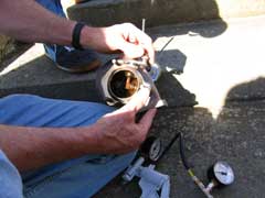
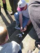
Lotus Engineer Geoff Davidson demonstrates at the LEW Oxford Meeting, August 2005EXHAUST MANIFOLD. TURBOCHARGER & WASTEGATE
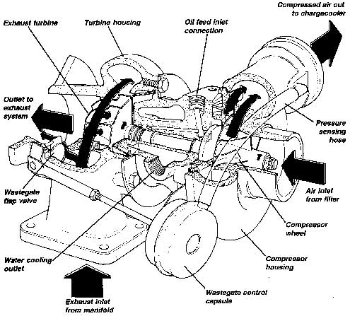
The cast iron exhaust manifold converges the gas streams from four branches into two, joining cylinders 1 with 4, and 2 with 3. These two gas streams are kept separated up to the turbine housing of the Garrett Airesearch type TB03 turbocharger which incorporates a water cooled bearing housing and integral wastegate.The exhaust gases spin the turbine wheel at speeds up to 100,000 rpm, before exiting the turbocharger and flowing through the catalytic converter and exhaust silencer. The turbine wheel is fixed to a short shaft supported by fully floating bearings in a water cooled housing, with the other end of the shaft carrying the compressor wheel. The compressor draws filtered air from the airbox and centrifuges the air out of the compressor housing into the air/water chargecooler, where the hot, compressed air is cooled by a circulated water supply before entering the intake plenum chamber.
The extent to which the intake air is compressed is dependent primarily on throttle opening and engine speed, but is mechanically limited by the action of an exhaust wastegate, which is designed to open at a specified boost level and bleed exhaust gas away from the turbine through a by-pass channel. The wastegate consists of a coil spring/pneumatically operated flap valve fitted between the turbine housing inlet and outlet which, when opened, diverts a proportion of the exhaust gas away from the turbine to limit the boost pressure built up in the inlet. The flap valve is linked to an pneumatic capsule which contains a spring to hold the valve shut, and a diaphragm pressure chamber connected by a hose to the boost pressure at the compressor outlet. As boost pressure builds up, the force in the pressure chamber, opposing the spring pressure, rises until the flap valve is opened.
In order to allow for controlled boost pressure in excess of this mechanical setting, a solenoid valve is fitted into the boost pressure sensing hose and under the control of the engine management ECM, is able to bleed off a proportion of the hose pressure in order to delay the opening of the wastegate and allow a higher boost pressure to be developed. As an engine safeguard, in case of a boost control system failure, the ECM will shut off the fuel pump and ignition if boost pressure in excess of 1.03 bar is detected for more than three seconds. For full details see section EMH.2 - T.
The turbocharger bearings are supplied with an oil feed from the oil gallery cover at the right hand rear of the block, and an oil drain hose is provided to return oil to the left hand side of the sump. In order to help protect the turbocharger bearings from the effects of heat soak after the engine has been stopped, a water feed and return system is provided, and connected between the heater take-off at the rear of the block and the header tank. Water circulation around the bearings continues after engine switch off, by thermo-syphon action,
and reduces the possibility of carbonisation of the oil in the turbocharger.The turbocharger unit is, with the exception of the wastegate capsule, a non-serviceable item which must be renewed if faulty. A certain amount of free play in the shaft bearings is a design feature, and should cause no conuem unless the amount of play allows the turbine or compressor wheels to contact any part of their housings. The shaft should turn freely and smoothly and the turbine and compressor blades should be free form signs of mechanical damage. Note that great care must be taken when working on the engine to prevent any foreign bodies from entering the turbocharger or the wheels will be severly damaged.
Wasteaate Capsule Replacement
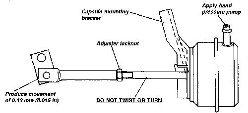
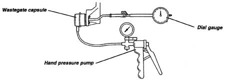
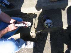
To remove the capsule, pull off the pressure sensing hose, remove the circlip from the flap valve operating arm to release the actuator rod, and release the two capsule fixing nuts. After fitting the new capsule, it is necessary to set the actuator rod length to achieve the specified maximum boost pressure of 0.65 bar (9.5 Ib/sq.in). For this purpose a hand pressure pump (e.g. seat lumbar support bulb) and 0 - 0.7 bar (0 - 10 Ib/sq.in) pressure gauge are required:Apply pressure to the capsule, and observe the pressure required to produce an actuator rod movement of 0.40 mm (0.015 in).
Specification = 0.58 + 0.02 bar (8.6 rt 0.25 Ib/sq.in)If the pressure is below specification, the actuator rod should be shortened, and if above specification, lengthened.
CAUTION: Do not turn, twist or force the threaded actuator rod emerging from the capsule and affixed to the diaphragm. Hold this rod stationary whilst slackening the locknut and screwing the extension piece on or off the actuator rod as required.
When the correct specification has been achieved, fit the rod onto the flap valve arm with the circlip, and connect the pressure sensing hose.
Note:
i) The practice of ‘revving’ the engine before switching off should be discouraged since the turbo will continue to spin, due to its inertia, after the engine has stopped and the pressurised oil supply has ceased.ii) After a fast run, the engine should be allowed to idle for a few minutes before switching off in order to maintain oil circulation whist the turbo cools down and prevent oil carbonisation from heat soak.
V8 WASTEGATES
TURBO BOOST CONTROL
Problems with turbo boost pressure may be mechanically or electronically derived. The base mechanical setting of the wastegate capsule should allow 0.35 bar (5.0 lb/i@ to be developed. If this cannot be achieved, the cause may be general engine condition and tuning, a broken wastegate capsule spring, seized or stiff wastgate linkage, or a leaking or burnt wastegate valve seat. Check cylinder compressions, valve timing and other basic tuning parameters, and for the free, spring loaded, operation of the wastegate. Inspection of the wastegate seat condition is possible after removal of the exhaust pipe from the turbocharger.The wastegate capsule and actuating rod are calibrated by the turbocharger manufacturer and can be checked using a dial gauge and hand operated pressure pump with 0 - 1 bar (15 lb/inn) pressure gauge:
CAUTION: Do not turn, twist or force the threaded actuator rod emerging from the capsule and affixed to the diaphragm. Hold this rod stationary whilst slackening the locknut and screwing the extension prece on or off the actuator rod as required. Refit to the wastegate lever arm and recheck pressure setting.
The wastegate capsule may be removed by disconnecting the pressure hose, uncoupling the actuator extension from the wastegate lever arm, and releasing the two nuts securing the capsule to the mounting bracket. If the problem is excessive boost pressure, the cause may be either mechanical or electronic. To verify the mechanical control, temporarily by-pass the solenoid valve and connect each wastegate capsule directly to the intake plenum. If over-boosting still occurs, the cause is mechanical. Check the following:
If the cause of over-boosting is electronic, check the solenoid valve and ECM control. The turbo boost control solenoid valve is located at the RH front of the engine bay and is connected between both wastegate capsules and the intake plenum. The valve is pulse width modulated by the ECM dependent on throttle opening, engine speed and knock signal. The ‘Tech 1’ scanner tool can display the duty cycle as a percentage of the time for which the valve is open: 0% = de-energised valve, intact pressure line to wastegate. 100% = valve energised 100% of time, pressure line fully ventilated. The ‘Tech 1’ tool is also able to conduct output tests on pulse width modulated components, including the wastegate solenoid valve.
A problem with the boost control circuit should cause a trouble code P141O/P1411/P1412 to be set. Refer to the diagnostic procedures in section EMM.4.
|
|