Esprit Gearbox
Renault TransmissionThe transmission assembly comprises of the clutch housing, five speed gearbox, crownwheel and pinion and differential. The transmission is built by Renault specifically for the Esprit application, with the 'high torque' version introduced for '93 MY designated 'UN1 026' (previously 'UN1 016') and identifiable by an i/d plate attached to the rear cover, and by the gear selector cross-shaft emerging from the right hand side (previously left) of the rear cover. Note however that VINs P 0001, P 0002, P 0003 and P 0004 were fitted with UN1 016 transmissions updated to 'RH shift'. The 1996 V8 model saw the introduction of the type UN1 027 version of the transmission, with a higher 5th gear ratio, reverse gear brake, and from '98 MY onwards, a modified cross shaft for the revised gear cable linkage without translator mechanism. During '98, the GT3 model adopted a UN1 028 variant which is based on the 027 bype but with lower final drive and third gear raitos.
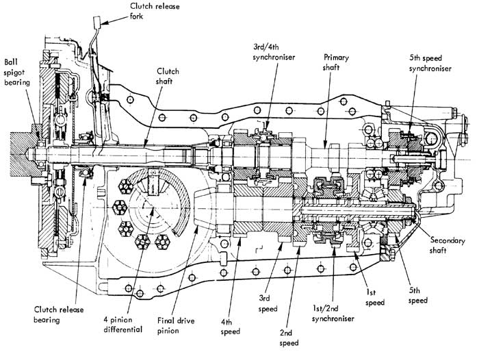
The gearbox is in two shaft all indirect five speed manual, with drive passing in via the upper, primary shaft, and out via the lower secondary shaft, onto the front end of which is formed an integral final drive spiral bevel pinion. Synchromesh is fitted to all forward speeds, with the 1st/2nd synchroniser mounted on the secondary shaft, the 3rd/4th synchroniser on the primary shaft, and the 5th synchroniser on the 'overhung' rear end of the primary shaft.
Reverse gear is achieved by sliding an idler spur gear into engagement with both a drive gear integral with the primary shaft, and the spur gear teeth machined on the outside of the 1st/2nd synchroniser assembly. Synchromesh on 3rd/4th and 5th gear is of the conventional Borg-Warner type, whereas that on 1st/2nd gear is of the inverted cone type for maximum cone surface area.
A clutch shaft, which carries the friction plate on 21 splines is supported at its front end by a ball type spigot bearing in the crankshaft, and is connected at its rear end by a roller bearing at the front, and a double ball bearing at the rear, whereas the secondary shaft uses a roller bearing at the front and a dual taper roller bearing at the rear. Needle roller bearings are used on each of the 'free' pinions.
Final Drive
The final drive assembly is incorporated into the front end of the transmission casing between the clutch housing and gearbox, and shares a common oil supply. A spiral bevel gear crownwheel and pinion is used, with a four pinion bevel gear differential.
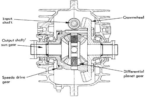
Short splined shafts, integral with the differential sun gears, project through each side of the casing where they carry the inboard C.V. joints of the drive shafts. The crownwheel/differential carrier assembly is supported by taper roller bearings which are adjustable for pre-load. There is no provision for any adjustment of final drive pinion depth or crownwheel and pinion backlash.
The speedo drive gear is mounted onto the differential carrier and mates with a driven pinion located in the right hand side of the casing.
Gearchange Mechanism
Four selector shafts lie along the right hand side of the gearbox, and are operated by a cross shaft with a single actuating finger. A slotted interlock guide prevents more than one selector shaft being moved from the neutral position at any one time.
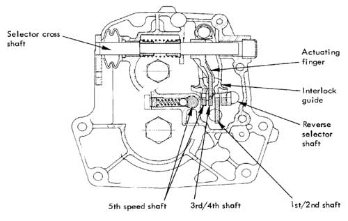
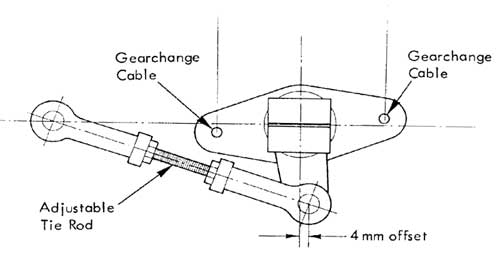
The cross shaft projects from the left hand side of the gearbox rear housing, and is fitted with a swivel 'tree' device to which the two gearchange cables are connected. These two push-pull cables are used to transfer movement from the gearchange lever to the swivel tree, which translates the motion into rotational and axial movement of the cross shaft.
The second gear selector fork is operated by it's selector shaft via a compression spring, which ensures a rapid (delayed) action of the synchroniser mechanism regardless of gearlever movement speed for optimum synchronising action when engaging 2nd gear.
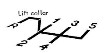
The gearchange lever is spring biased towards the 3rd/4th gear plane, and must be moved against light spring pressure to the left before selecting 1st or 2nd gear, and against similar pressure to the right to select 5th gear. The selection of reverse gear is inhibited by a plate at the base of the gear lever, above which a stop end pad must be raised by lifting a collar beneath the gear knob.
This allows the lever to be moved fully leftwards and to the rear to engage the gear.
Transmission Lubrication
The gearbox and final drive share a common oil supply for which square headed drain and filler/level plugs are provided. The drain plug is located in the forward underside of the unit, and the filler/level plug in the left hand side, just forward of the gearbox mounting bracket.

The oil level should be checked at every service interval, and the oil changed at 'C' services (every 24,000 miles).
Drain the transmission when the oil is warm so that it flows more readily, and whilst the impurities are held in suspension. Clean the replace the drain plug when the old oil has drained thoroughly and refill ONLY with specified oil up to the level plug hole (approx. 3 litres). Clean and replace level plug.
Mobile SHC 630M is a fully synthetic transmission lubricant and is the ONLY oil approved for this application. Order from the Service Parts Department under part no. AO82F6356V.
Gearchange mechanism adjustment
A two cable mechanism is used to connect the gearchange lever to the gearbox cross-shaft. The gearchange lever assembly is arranged to provide a pull or push equally to both cables when moved in the fore/aft plane. When the lever is moved side to side (crossgate), the mechanism provides a pull to one cable and a push to the other. At the gearbox end this cable movement is converted via a 'translator' into rotational or axial movement of the gearbox cross shaft.
![]()
The translator consists of two parts: a swivel 'tree' and a pivot pin, the pivot pin hangs from a splined clamp which is secured to the cross shaft extension. The swivel tree which pivots on this pin via two ball bearing races, has two diametrically opposed arms at its lower end and a single arm disposed at 90° to the others, at its top end.
When the two gearchange cables pull or push together, the lower end of the translator is pulled or pushed, and a rotation imparted to the cross shaft. When one cable pulls and the other pushes, the translator is rotated about its vertical axis, but since the top arm of the translator is connected by a tie rod to a fixed bracket, the translator itself must pivot around the outer end of its top arm, thus imparting an axial (lateral) movement to the cross shaft.
Gearchange Cable Adjustment Procedure
Adjustment of the gearchange cables can only be checked after disconnecting the ball joint on the rear end of each cable from the translator.1. Disconnect both cable ball joints from the translator.
2. With the transmission in neutral, the gearbox cross shaft is spring loaded axially to the 3rd/4th gear plane. If necessary, adjust the translator tie rod so that the tie rod fixing hole in the translator upper arm is offset 4mm inboard of a fore/aft datum line passing through the centre of the translator clamp.
3. The gearchange lever is independently spring loaded to the 3rd/4th gear plane. With the aid of an assistant, hold the gear lever leaning backwards approximately 7.5° in this crossgate plane.
4. If necessary, adjust the length of the two cables at their rear end ball joints so that they can be connected to the translator without preload. Note that both gearchange cables are identical and that the right hand cable at the gearlever end is fitted to the left hand side of the gearbox end. As a check, move the gear lever across the gate from right to left and observe cable movement at the rear end. The cable that moves forward is fitted to the left hand side at the gearbox.
Reverse Inhibitor Setting
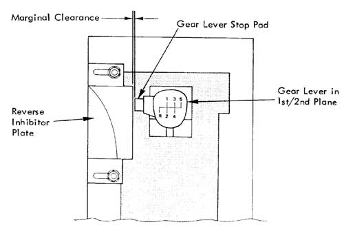
The gearchange lever assembly incorporates a reverse inhibitor which necessitates a collar beneath the lever knob to be raised before the lever may be moved fully to the left, and then rearwards, to select reverse gear. Raising of the collar causes a stop pad to be lifted above an inhibitor plate allowing the lever to be moved fully leftwards. The reverse inhibitor is correctly set if the first and second gears may be obtained without obstruction, but reverse gear cannot be selected without first lifting the gear lever collar.Before any adjustment to the inhibitor plate position is made, first check that the gearchange cables are correctly adjusted. (see above).
If necessary, remove the centre console and gear lever lower gaiter for access, and adjust the position of the inhibitor plate for marginal clearance between it, and the gear lever pad when the lever is moved in the 1st/2nd plane.
Basic History of UN1 Gearbox
All the UN1 Lotus Gearboxes are very similar. This is the 'simplified' history.
UN1 – 016 – 4 Cylinder G/Box – First variant of Lotus UN1– First used on X180 Introduction in 1988. This 'Box had rear cover with L/H shift lever.
UN1 – 026 – High Torque G/Box – Stronger Casings etc. introduced circa 1993. This 'Box had rear cover with R/H shift lever
UN1 – 027 – V8 Gearbox – Introduced in 1996 on V8 Esprit. This box was basically similar to 4 Cyl High Torque unit with new Clutch
Housing. It carried over the R/H shift lever. It had synchro on Reverse Gear. A higher 5th gear. The shift mechanism was changed to an improved version of the R/H mechanism from VIN W2272 – this requires a different shift master unit and cables.UN1 – 028 – 4 cylinder G/Box for the Esprit GT3 (2.0 Litre) with a different Axle Ratio and Gear Ratios - this Axle Ratio is not suitable for 2.2 Litre Engine Torque.
In a nutshell the 026 & 027 Gearboxes are very similar except for the Clutch Housing, Synchro on Reverse, 5th Gear Ratio. The clutch Housings & Rear Cover (with shift lever) can be changed over easily. Minor improvements were introduced at the time of Sport 350 to improve durability.
The Lotus versions of the Box were very similar to Renault units at first sight. What people do not realise is that the Lotus versions had some very important differences. The main issue is the crownwheel & pinion. Although the Ratio is identical to some Renault vehicle applications the material is different. The Renault material will not survive the Lotus application (even the earliest non intercooled cars). Running on the approved oil is another critical item.
|
|