Esprit Cam belts
You need to change it, but when?Lots if discussion has taken place on the belt servicing and life. This page has information on both 4-cylinder Esprits and V8's. The cambelt is one consumable part that needs replacing as specified by the manufacturer. Not replacing these belts as advised could result in extensive and expensive damage to your engine if they do slip off or fail.
Lotus Esprit World doesn't recommend just going on the mileage for changing cam belts. They really should be changed every 2 years, even if your mileage is much lower than that specified. A hot engine bay, weather changes during the year and moisture all can have an affect on the life of one of these belts.
Lotus Esprit World has got the latest information on recommended renewal intervals for cam belts from Lotus Cars Ltd. We have also added information on checking, removing and replacing cam belts for 4-cylinder and V8's.
From Lotus Cars LtdLotus have checked all the Lotus Cars literature produced by their Technical Service department and circulated to Lotus Dealer network and concluded the latest situation is as follows :-
For non-USA Esprit V8 models.
A Class 2 Service Bulletin (No. 2000/18) was published and circulated to the Dealers on 9/10/00. This changed the belt renewal interval from 72,000 miles (120,000 km) to 24,000 miles (40,000 km). This was based on continuous monitoring and data analysis.This action was taken to ensure the design level of refinement is achieved with respect to belt generated noise, and to maintain complete customer satisfaction. At this time a revision to the procedure for replacing the cam belt was introduced (reduced time/cost).
The new procedure allows cam belt replacement without disturbing the intake plenum of cam covers, but requires a new special tool to hold the cam pulleys and facilitate the release of the pulley bolts (labour time of 4 hours). The belt should be checked for tension as previously at 12,000 mile (20,000 km) intervals (labour time 1.6 hours)
This update could not be applied to the USA Service Schedule due to legislation requirements. By introducing a belt change at 24,000 also reduces the risk of belt problems. The Data analysis collected over the first few years of vehicle servicing revealed that many cars were running with incorrect belt tension due to incorrect servicing. Lotus testing confirms that if the belts are run for a period at the incorrect tension (slack or tight) the belt life is reduced by a significant amount.
By introducing the 24,000 belt life Lotus felt that this would have a significant impact on the risk of belt failures and the associated
major/expensive engine damage no owner wants to experience.On the 4 cylinder engine.
Lotus have run many engines with the HTD Belt to 100,000 miles on the same belt. This was done in controlled conditions (on the road) where the belt tension was monitored regularly. All Lotus testing is done with calibrated test gear and trained technicians.Lotus know from experience that many service tools never have a regular check for accuracy and are often not used correctly. Based on this many engines are running with incorrect belt tension. If the belt is changed every 24,000 miles this is not a significant problem. To cater for any circumstances where the engine could have been running with incorrect tension the 24,000 belt life is considered suitable.
4-Cylinder Camshaft belts
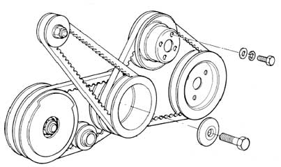
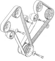
A single High Torque Drive (HTD) glassfibre reinforced synthetic rubber toothed belt is used to transmit drive from a toothed pully on the front of the crankshaft to larger diameter half speed pulleys on the front of each camshaft, and on the auxiliary shaft. A smooth pulley wheel mounted on a ball bearing with an eccentric hub, acts against the back of the belt to provide sufficient wrap around the crank pulley and enable adjustment of belt tension to be made.
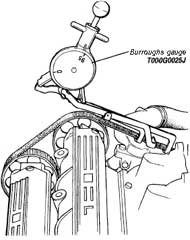
It is most important that the condition of the cam belt is carefully inspected, and its tension checked as specified in the Service Schedule, and that the belt is renewed every 36,000 miles. Always use the specified Burroughs Gauge to measure belt tension, as an over tightened belt will whine and may fail prematurely, whereas a slack belt is liable to 'jump' a cam pulley (especially on cold start up) and result in damage to the valve gear.
WARNING: Be aware of the danger caused by unprotected pulleys when the engine is running. Keep fingers and loose clothing well clear and take precautions against dropping tools, nuts/bolts etc into the belt/pulley system.
4-Cylinder Cam Belt Adjustment
Do NOT attempt to adjust belt tension on a hot engine. Carry out the following procedure only at an engine (ambient) temperature of between 15-25°C.
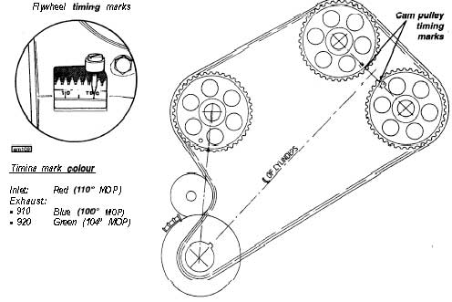
If the camshaft drive has just been reassembled, rotate the engine in the normal direction of rotation (clockwise viewed from in front) several times before setting at TDC. Use the timing marks and pointer on the fly-wheel rim and clutch housing aperture viewable after removing the protective rubber grommet in the top of the clutch housing.
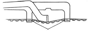
1. Fit cantilevered Burroughs Gauge between auxiliary and inlet camshaft pulleys as shown in the diagram, with the central arm resting on the flat side of the belt, and the two hooks on the toothed side, with the belt sitting fully on the hooks.
Care must be taken to ensure that no part of the gauge rests on the engine bay surround or thermostat housing etc. and that the hooks are not trapped between belt and pulleys.
2. Press and release the plunger knob several times to obtain a settled reading. Rotate the engine 360° and measure again. Repeat the procedure to obtain a third reading and average the results.
Correct belt tension = 95 units on the gauge
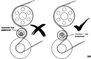
3. Before adjusting belt tension, first check the orientation of the belt tensioner: The eccentric should point downwards as shown so that any tendency for the eccentric to turn in operation will cause the clamp nut to tighten.
To adjust, slacken the clamp nut and use a 19mm spanner to turn the eccentric as required. Torque tighten clamp nut to 34 • 41 Nm (25 • 30 lb ft) and re-check belt tension.
4-Cylinder Cam Belt Removal/Replacement
It is important to realise that with the cam belt removed, Inadvertent turning of the camshafts or crankshaft may result in contact between the valves and pistons with consequent damage. The belt is removed with the engine in the 'timing position' and if it is then desired to turn the camshaft, the crankshaft should first be turned through 90° to bring the pistons to mid-stroke.
1. Drain cooling system and disconnect the radiator and heater return hoses from the water pump. Release the hose from the thermostat housing outlet elbow.
2. Turn the engine to the 'timing position' with the crankshaft at no 1 (firing) TDC and the timing dots on the camshaft pulleys facing towards each other. Use the timing marks and pointer on the flywheel rim and clutch housing aperture, viewable after removing the protective rubber grommet in the top of the clutch housing.
3. Slacken the remove all auxiliary drive 'V' belts.
4. Remove crankshaft pulley bolt and conical washer and withdraw triple 'V' pulley from crankshaft.
5. Remove triangular brace between alternator, water pump and belt tensioner bracket, taking carefully note of the positioning of all spacers and washers etc.
6. Re-check timing position before slackening the cam belt tensioner clamp nut and rotating the tensioner eccentric away from the belt. Slide the belt off the pulleys.
7. Before replacing the cam belt, check the condition of all toothed pulleys and the belt tensioner. Check that the camshafts and crankshaft are in the timing position as in (1) and slide the belt onto the pulleys. Rotate the tensioner eccentric counterclockwise to take up belt slack and temporarily tighten the clamp nut. Recheck cam timing.
8. Re-fit the 'V' pulley to crankshaft with conical washer and retaining bolt. Torque tighten to 79 • 81 Nm (56 • 60 lb ft).
Note: The above in the actually workshop manual has a printing error and reads 79 - 61 Nm, it should be as above 79 -81 Nm
9. Adjust cam belt tension (see above).
10. Re-fit triangular alternator brace taking care to fit spacers and washers as noted in (5).
11. Re-fit and tension all auxiliary drive 'V' belts in the order • a/c compressor, water pump/PAS pump, alternator.
12. Refit heater and coolant hoses to water pump and refill cooling system (see section KC).
13. Run engine for several minutes and re-check cam belt tension.
4-Cylinder Cam Belt Tensioner Removal/Replacement
1. Turn the engine to the timing position and tape the cam belt to both camshaft pulleys and auxiliary shaft pulley as an aid to re-assembly.
2. Slacken and remove all auxiliary 'V' Belts, remove crankshaft pulley bolt and conical washer and withdraw triple 'V' pulley from crankshaft.
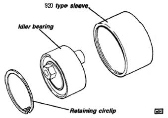
3. Remove tensioner clamp nut and withdraw eccentric and pulley/bearing assembly off the mounting stud. Press out the eccentric from the pulley/bearing hub.
4. To replace: Press the pulley/bearing onto the eccentric adjuster, fit onto the mounting stud and retain with a new nyloc nut.
Note: In order to utilise the common timing belt on both 2.2 and 2.- litre engines, the tensioner pulley on the 920 (2 litre) engine has a sleeve added to increase its diameter from 63 to 70mm. The sleeve is a press fit on the bearing and is retained by a shoulder and circlip.
5. Check that the cam belt is fitted correctly around the pulleys with all shafts in the timing position, and rotate tensioner eccentric counterclockwise to take up belt slack, and temporarily tighten clamp nut. Recheck cam timing.
6. Re-fit triple 'V' pulley to crankshaft with conical washer and retaining bolt. Torque tighten to 79 • 81 Nm (58 • 60 lb ft).
7. Adjust cam belt tensioner (see previous).
8. Refit and tension all auxiliary drive 'V' belts in the order • a/c compressor, water pump/PAS pump, alternator.
9. Run engine for several minutes and recheck cam belt tension.
Belt Tension Clavis Gauge
A Clavis electronic frequency meter (T000T1398F) was introduced for setting the cam belt tension on the Esprit V8 engine. Compared with a deflection based meter (Burroughs), the frequency measuring technique allows much closer control of belt tension, with improved ease of operation and repeatability, and a consequent reduction in specified tolerance. In order for these benefits to be applied to the Lotus 4-cyinder 912/910/920 engines, the following belt tensioning procedure should be used on all such engines equipped with the 'HTD' (rounded tooth profile) type cam belt.To check/adjust belt tension:
1. Remove the 4 spark plugs, and rotate the crankshaft clockwise until the crank pulley notch aligns with the 30° BTDC front cover mark. The timing dots on the inlet and exhaust cam pulleys should be towards the centre, but not aligned. Rotate the crank a further 360° if necessary.2. Measure the timing belt frequency using the Clavis gauge between the auxiliary shaft and inlet cam pulleys (NOT on any other belt run). When tapped with a suitable instrument (e.g. screwdriver) the meter should read: Specification = 100 to 110 Hz
3. If necessary, slacken the tensioner clamp bolt and turn the eccentric hub as required to adjust the belt tension (turn counterclockwise to increase tension). Tighten the clamp nut to 34-41 Nm. Rotate the crankshaft 720° clockwise and re-check belt tension.Note: Do not turn the crankshaft backwards (counterclockwise) at any stage of the procedure.
4. After fitting a new cam belt, it is advisable when possible, to re-check the tension after 500 miles.
See here or a guide (non-LEW page) http://www.rottenrodent.com/lotus/tb1.htm
V8 Cam drive belts & Cam TimingA two stage drive is used for the twin overhead camshafts of each cylinder bank. The first stage comprises an inverted tooth 'Morse' chain from the crankshaft to an intermediate shaft housed within the front cover. The second stage uses separate, synthetic, straight toothed, HTD profile belts for each cylinder bank, driven from two pulleys on the intermediate shaft, each belt using a smooth pulley/bearing mounted on an eccentric hub to bear against the back of the belt and facilitate belt tension adjustment. In order to achieve the optimum accuracy of valve timing, all the toothed pulleys are clamped to their shafts without the positional constraint of indexing keys. A crankshaft positioning tool and four camshaft setting pins can be used to set each of the shafts in a ‘timing’ position, corresponding to 10° BTDC no.2 cylinder firing. Great care must be taken if the cam drive system is disturbed, in order to avoid valve to piston contact.
CAUTION; The engine should be turned only in the normal direction of rotation; i.e. clockwise as viewed from the front. Turning the engine backwards causes cam drive loading to be applied to the belt tensioners, and may result in loss of valve timing due to a cam belt jumping teeth.
V8 Cam Timing Verification
Special tools required:
Crankshaft Position Tool & Camshaft Tolerance Pin.
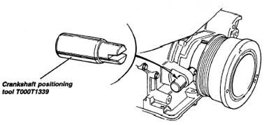
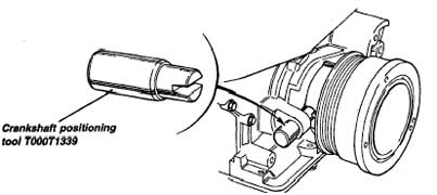
It is important to realise that the positions of the toothed pulleys themselves are not relevant to cam timing, as there is no indexing of any of the pulleys to their shafts. If the cam timing needs to be checked, it is necessary to establish the positions of the camshafts themselves, using camshaft position ‘tolerance’ pins, T000T1345, and a crankshaft positioning tool T000T1339. Removal of the cam covers is not necessary.
a) Release the single fixing screw, and remove the crankshaft sensor from its plinth on the front cover. Turn the engine to align the marked vane on the crankshaft front pulley (1 marked, 3 unmarked) with the sensor plinth. Fit the crankshaft positioning tool T000T1339 into the plinth and engage onto the marked pulley vane. This fixes the crankshaft at 10° BTDC no.2 cylinder (note that there is no visual indication whether this is exhaust/intake or firing TDC).
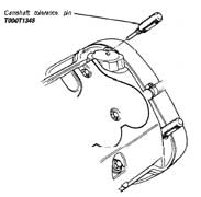
b) Remove the pair of front most fixings from both camshaft covers, and insert a camshaft position tolerance pin T000T1345 into each of the four fixing holes. Note that the ‘tolerance’ pins should not be confused with the ‘setting’ pins, which are similar but of larger diameter:
Tolerance Pin T000T1345 4.2 mm diameter
Setting Pin T000T1337 4.7 mm diameterWhen no.2 cylinder is at 10° BTDC on the firing stroke, the tolerance pins should engage fully with a positioning hole in each camshaft. It may be necessary to remove the crankshaft positioning tool and turn the crankshaft 360° to move from the exhaust/intake TDC to the firing TDC, and refit the positioning tool.
c) Having established the correct (firing) TDC, if the tolerance pin cannot be fully inserted into each of the holes, the cam timing is outside specification. A small variation in cam timing can occur without consequent damage, but an error of one belt tooth or more may result in valve to piston contact and associated damage. If the engine is operative, measure the cylinder compressions to check for valve sealing, and if satisfactory, reset the cam timing as detailed in the later procedure.
V8 Cam Belt Tensioning
Each of the two cam belts uses a smooth pulley wheel bearing against the back of the belt via an eccentric hub, in order to facilitate adjustment of belt tension. An electronic frequency meter (‘Clavis’ gauge) is used to accurately measure belt tension. Note that the same belt tension reading is used for each of the two belts, but that the mirror imaging of the inlet and exhaust camshaft layout between LH and RH heads results in the tension being set at different camshaft positions for each cylinder bank - LH bank at 90° ATDC No.2 (TDC No.6 & 7); RH bank at 135° ATDC No.2 (45° BTDC No.1 & 4).
Special tools required:
Clavis Gauge T000Tl396
Tensioning Tool T000T1360
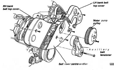
Timing Disc T000T13911. Remove the auxiliary drive belt and tensioner (sub-section ED.3), and water pump pulley.
2. Remove the four bolts securing the three section cam belt cover, and remove the cover.
3. Release the single retaining screw, and remove the crankshaft sensor from the plinth in the front cover. Turn the crankshaft clockwise until the crankshaft positioning tool T000T1339 can be inserted through the sensor plinth to engage the marked vane on the crankshaft pulley (Note: one marked vane, three unmarked). This positions the the crankshaft at 10° BTDC no.2 cylinder.
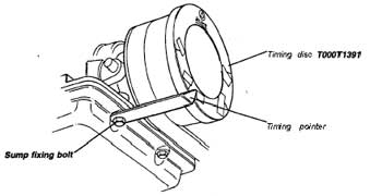
4. Make up a timing pointer (e.g. fixed by the sump fixing bolt), with the point adjacent to the crankshaft front pulley. Secure the timing disc to the front pulley using a few dabs of putty or double sided tape, with the disc positioned to align the ‘10° BTDC No.2 cylinder’ mark with the pointer. Note that one side of the timing disc is designed to be used with a mirror.
5. Remove the crankshaft positioning tool, and turn the crankshaft clockwise to align the ‘90° ATDC No.2 cylinder’ mark with the tim-
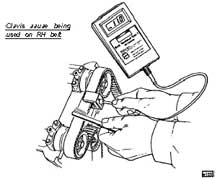
Ing pointer.6. Measure the LH cam belt tension using the Clavis gauge between the two camshaft pulleys (NOT on any other belt run).
Specification = 95 - 120 Hz
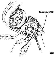
7 . If necessary, slacken the tensioner clamp bolt, and use special tool T000T1360 to turn the eccentric hub as required to adjust belt tension. Torque the clamp bolt to 20 Nm and recheck belt frequency.
8. Turn the crankshaft clockwise to align the ‘135° ATDC No.2 cylinder’ mark with the timing pointer.
9. Measure the RH cam belt tension using the Clavis gauge between the two camshaft pulleys (NOT on any other belt run).
Specification = 95 - 120 Hz
10. If necessary, slacken the tensioner clamp bolt, and turn the eccentric hub as required to adjust belt tension, and torque the clamp bolt to 20 Nm. Recheck belt frequency.
11. Remove the timing pointer and disc and refit the cam belt covers.
V8 Valve Timing Resetting Procedure
Special tools required:
Crankshaft Positioning Tool T000T1 339
Camshaft Setting Pin T000T1337 (4 off)
Camshaft Tolerance Pin T000T1345 (4 off)
Camshaft Clamping Cap T000T1336 (4 off)
Clavis Gauge T000T1398
Tensioning Tool T000Tl360
Timing Disc T000T1391If the intermediate shaft pulley bolt is to be checked or tightened:
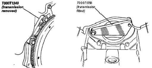
Flywheel Locking Tool (transmission fitted) T000T1358 or;
Flywheel Locking Tool (transmission removed) T000T1249
Crankshaft ‘Safe’ Position: Whenever the cam timing is disturbed it is most important to guard against damage from valve to piston contact. In order to park the crankshaft in a ‘safe’ position:a) Remove the crankshaft sensor from its plinth, and fit the crankshaft positioning tool. Turn the engine to its timing position, with the marked vane on the crankshaft front pulley (1 marked, 3 unmarked) aligned with the positioning tool, and the holes in the camshaft front bearing caps aligned with the camshaft drillings. This is 10° BTDC no.2. No.2 cylinder may be approaching TDC on the inlet/exhaust stroke, or the firing stroke. Check the alignment of the camshaft drillings with the holes in the camshaft front bearing caps, and if necessary, turn the crankshaft 360° in order to align the holes, as will occur on the firing stroke. Locate the positioning tool onto the crank pulley vane.
b ) Make up a timing pointer and secure by a sump fixing bolt, with the point adjacent to the crankshaft front pulley. Secure the timing disc to the front pulley using a few dabs of putty or double sided tape, with the disc positioned to align the ‘10° BTDC No.2 cylinder’ mark with the pointer. Note that one side of the timing disc is designed to be used with a mirror.
c) Withdraw the positioning tool and turn the crankshaft just short of two complete revolutions, to align the“ 45” BTDC No.2 ‘Safe’ Position” mark on the timing disc with the pointer. In this position, no piston is near the top of its stroke.
intermediate Shaft Pulley Bolt: If the intermediate shaft pulleys have been replaced, or if the intermediate shaft pulley bolt needs to be checked or tightened, the flywheel needs to be locked in order to resist the torque. Two tools are available for this purpose; With the engine ‘in situ’, or if the transmission is fitted, locking tool T000T1358 is available to fit via the starter motor aperture (first remove intake plenum (ED.4) and starter motor). If the transmission is removed, tool T000T1249 may be used:
i) Park the crankshaft in the ‘safe’ position (see above) before fitting either of the flywheel locking tools.
ii) Remove the auxiliary drive belt and tensioner (sub-section ED.3) and water pump pulley.
iii) Remove the four bolts securing the three section cam belt cover, and remove the cover.
iv) Check that the correct intermediate shaft pulley bolt (A918W5225F) is fitted, identifiable by its flanged (integral washer) head, together with a separate clamping washer. Tighten the pulley bolt to 125 Nm (92 Ib ft). Note that the positioning of the pulleys is not important.
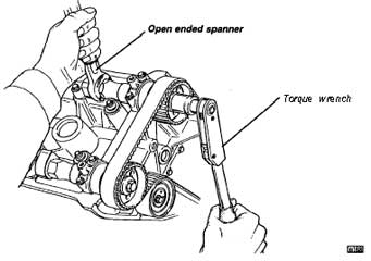
Setting the Valve Timing: To set the valve timing, the cam pulley retaining bolts must be slackened. This operation requires the removal of the intake plenum and cam covers in order to allow the camshafts to be restrained whilst torque is applied to the pulley bolt - DO NOT allow the checking/positioning pin to resist the applied torque, or the pin and/or associated parts will be damaged.
1. If not already removed, remove the top part of each cam belt cover.
2. Remove the intake plenum (see sub-section ED.4) and cam covers. Set the engine in the ‘safe’ position (see above).
3. Use a 23 mm open ended spanner on the hexagonal shank of each camshaft in turn, in order to hold the camshaft whilst the cam pulley retaining bolt is removed.
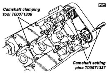
4. Rotate each of the camshafts in turn to enable a camshaft position setting pin T000T1337 to be inserted through the front bearing cap and into the camshaft drilling. (Note that the setting pins are of larger diameter than the tolerance pins.) Remove camshaft bearing caps 3 & 4 from each camshaft, noting the match mark letter or number on each cap, and fit a clamping tool T000T1336 to each camshaft, tightening the bolts to 6 Nm (6 Ib ft). Check that the setting pins can still be freely inserted.
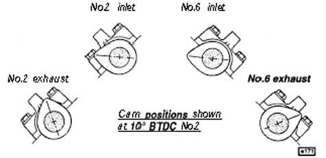
Note: Some very early engines may have camshafts with two drilled holes; one for timing at 10° BTDC no.1 cylinder, and one for 10° BTDC no.2 cylinder. Use only the no.2 cylinder drillings, identifiable by the cam lobe positions of cylinders 2 and 6 as shown.
5 . Clean the threads of the cam pulley bolts before applying Loctite 572 (A912E7030V), and re-installing, nip tightening each cam pulley bolt to only 7 Nm (5 Ib ft) at this stage.
6. With the camshafts still locked, turn the crankshaft clockwise, dragging the cam pulleys just until the crankshaft positioning tool T00011339 can be inserted through the sensor plinth to engage fully with the marked vane on the crankshaft pulley (timing disc will read 10° BTDC No.2 cylinder). If the crankshaft is inadvertently turned too far, do NOT reverse direction, but continue clockwise for a complete revolution.
7. Remove the setting pins before holding each camshaft in turn using a 23 mm open ended spanner on the flats of the shaft, and torque tightening the cam pulley bolt to 100 Nm (74 Ib ft).
8. Remove the camshaft locking caps and crank positioning tool. Refit the standard cam caps and torque tighten to 8 Nm (6 Ib ft). Carefully rotate the engine through two complete revolutions, checking for any tendency to lock up, indicating a possible valve timing error and valve to piston contact.
9. Check, and if necessary adjust the cam belt tension (see earlier).
10. Refit the crankshaft positioning tool and check that a camshaft tolerance pin T000T1345 fits into each camshaft drilling, noting that this pin is of smaller diameter than the setting pins to allow for an acceptable tolerance stack up. If the pin fits in all the shafts, the timing is correct.
11. Refit remaining components as necessary.
V8 Cam Belt Replacement
Special tools required: Crankshaft Positioning Tool T000T1339
Camshaft Tolerance Pin T000T1345 (4 off)
Clavis Gauge T000T1398
Tensioning Tool T000T1360
Timing Disc T000T1391
1. Remove the auxiliary drive belt, auxiliary belt tensioner and water pump pulley. Release the four screws securing the three sections of the cam belt cover, and remove the cover.2. To avoid draining the power steering fluid, remove the three bolts securing the power steering pump mounting bracket to the head, release the hose routing clips as necessary, and support the pump clear of the engine.
3. Release the single fixing screw, and remove the crankshaft sensor from its plinth on the front cover. Turn the engine to align the marked vane on the crankshaft front pulley (1 marked, 3 unmarked) with the sensor plinth. Fit the crankshaft positioning tool T000T1339 into the plinth and engage onto the marked pulley vane. This fixes the crankshaft at 10° BTDC no.2 cylinder (note that there is no visual indication whether this is exhaust/intake or firing TDC).
4. Remove the pair of front most fixings from both camshaft covers, and insert camshaft position tolerance pins T000T1345 into each of the four fixing holes. Note that the ‘tolerance’ pin should not be confused with the ‘setting’ pins, which are similar but of larger diameter:
Tolerance Pin T000T1345 4.2 mm diameter
Setting Pin T000T1337 4.7 mm diameterWhen no.2 cylinder is at 10° BTDC on the firing stroke, the tolerance pin should engage fully with a positioning hole in each camshaft. It may be necessary to remove the crankshaft positioning tool and turn the crankshaft 360° to move from the exhaust/intake TDC to the firing TDC, and refit the positioning tool.
5. Release the tensioner clamp bolts, and slide both cam belts off the intermediate and camshaft pulleys. Note that if the same cam belt is to be refitted, the direction of rotation should be marked on the belt before removal to enable this orientation to be maintained. Ensure that both cam belts are 106 tooth, and the tensioner pulleys 73 mm diameter (early cars 107T and 60 mm diameter).
6. Slide the new belt onto the LH pulleys ensuring that the drive side run, and the span between the two cam pulleys, are both tight with no ‘extra’ belt tooth. Use tool T000T1360 to rotate the tensioner hub and take up the belt slack before tightening the clamp bolt. Repeat the operation for the RH belt.
7. Remove the camshaft tolerance pins.
8. Refer to ‘Cam Belt Tensioning’ above to set the tension on both belts.
9. Turn the crankshaft over 1% times clockwise, and refit the crankshaft positioning tool onto the marked pulley vane. Check that the tolerance pins may still be fitted into each of the four camshafts. If not, then the ‘Valve Timing Resetting Procedure’ must be followed to bring the valve timing into tolerance.
10. Refit cam belt covers, auxiliary belt and other removed components.
|
|