Camshaft Driving Belt
Removing, Replacing and Tension Check
From Service Manual
BELT TENSIONS
Toothed timing belt (133 teeth)
With both types of belt tensioners set the belt tension to an average reading of 90-95 units cold (120-125 units hot). Check toothed belt tension between auxiliary and inlet camshaft pulley, with Burroughs Gauge Type BT-33-86A 5-20.IMPORTANT: Check the b elt tension with number 1 or 4 cylinder at TDC after rotating engine at least one full turn clockwise (norrmal running direction). Repeat thls operation twice to obtain specified average reading.
V-belt compressor - 9 mm (0.35 ins) Deflection
Other V-belts - 12 mm (0.50 ins) Deflection
CAMSHAFT DRIVING BELT (TOOTHED BELT)
The camshaft driving belt i s fitted with an automatic belt terlsioner assembly (early
vehicles are fitted with manual adjusters). Check the adiustrnent of the driving belt
at service intewals and if the belt is removed or a new belt is fitted.

Belt Tension Check
Check the belt tension using a Burrough's Gauge BT-33-86A 5-20 fitted between the
auxiliary shaft sprocket and the inlet camshaft sprocket. Check TECHNICAL DATA
for the correct tension.
1. Fully extend the hook by pushing handle completely down.
2. Insert the belt between nose piece and hook, ensuring hook is between belt teeth.
3. Release handle with a rapid action. A slow release will result in a high reading, which is caused by a small amount of internal friction stopping the hook returning fully. Read off the tension in pounds indicated by the pointer on the handle. Repeot several times to ensure a correct reading.
4. Rotate the engine crankshaft by hand approximately 120° in the direction of rotation. Repeat operations 1, 2 and 3 taking the average of three readings for the mean belt tension.

To Remove Timing Belt
1. Set the engine in the timing position with number one cylinder piston at T.D.C. Align the timing mark on the crankshoft 'V' pulley or flywheel with timing pointer. At this point the marks on the camshaft sprocket should also be aligned with each other (figure 12).
2. Loosen the alternator fixing bolts and remove the 'V' drive belt and the crankshaft 'V' pulley.
For manual adjusters release the belt tension and remove the driving belt.
4. For automatic adjusters remove the alternotor odjusting strap, together with the nut ond bolt. Swing the alternotor up ond secure in the 'up' position to allow access to the tensianer adjusting screw. Accessibility can be improved if the olternator is completely removed.
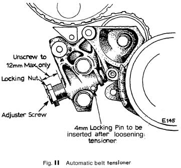
5 . Slacken off locknut and release adjusting screw by turning counter-clockwise until the adjusting screw is protruding a maximum of 12 mm (0.5 in) from the tensioner hawing

6. Force idler wheel towards tensioner body, this can be achieved by pulling on the timing belt, until the groove on the piston lines up with the locking pin hole in the housing. Insert a 4 mm diameter pin in the hole and release the belt. The pin will prevent the assembly being forced apart by the tension spring.
WARNING: The locking pin MUST be fitted to the tensioner housing every time
the toothed belt is removed or slackened off.
Do not under ony circumstances attempt to remove the locking pin
from the tensioner assembly, unless the unit i s fitted to the engine with
the belt in position.
To Replace
1. Reverse the removal procedure. Before refitting the drive belt check the
following:
(a) Rotor arm is in- c.o rrect h i o n , with number one cylinder piston at T.D.C.
(b) Exhaust and Inlet spro.. c. ket are correctly located, see figure 12.
(c) Crankshaft sprocket or fi)wheel TDC mark is in line with pointer, see
figure 12.
(d) Ensure the peg Qn the inside of the rubber buffer (fitted to the tensioner
body) is centred in the adjuster piston hole.
2. Fit toothed belt to pulleys. Pull the belt sufficient to force the idler bearing on tensioner towards tensioner body. Remove locking pin and release pressure on belt.
3. If on auxiliary pulley snubber is fitted, adjust it for a ciearance of 0.4 mm -+ 0.1 mm (.016+- .004 in) between the pad and toothed belt.
4. Refit crankshaft 'V' pulley and adjust belt tension.
NOTE: Do NOT attempt adjustment of the belt if the engine is hot. The ambient
temperature of the engine should be between 15°C to 25°C for the
following adjustment procedures.
1. Turn adjusting screw in a clockwise direction untiI the specified tension is
recorded on the Burroughs Gauge (see Technical Data).
2. Ensure crankshaft is at TDC, after rotating a minimum of one turn clockwise.
3. Tighten adjusting screw locknut ond refit alternator.
DRIVING BELT TENSIONER
To Remove
1 . Set engine in the timing position with number one piston at T.D.C.
2. Align the timing marks on the crarnkshaft 'V' pulley or flywheel with timing pointer (figure 12).
3. Loosen the alternator fixing bolts and remove 'V' drive belt and the crankshaft 'V' pulley.
4. For manual adjusters:
(a) Release the securing rlut and washer retaining the tensioner pulley
and slacken the drive belt.
(b) Fully remove the tensioner securing nut and washer, then pull the
adjuster from out of the front cover. The adjuster is a sliding fit on its locating stud in the cylinder block.
5. For autornatic adiusters:
(a) Remove the alternator together with the adjusting strap arid fixing
nuts and bolts.
(b) Release the tension on the driving belt.
(c) Remove the lower fixing bolt and remove the nuts securing the adjuster to the fixirig stud, slide off the automatic adjuster.
If you have any comments, feel free to e-mail us with at admin@lotusespritworld.com
![]()
|
|